Sharingan is a robot designed to achieve the project objective of Operating system subject at Eurecom. The main objective of the game is to score points by identifying objects and sending balls into the opponent’s area. Each time you identify an object, you should inform the server about the identified object and about its position.
Now that the objective is defined, we look at the rules to be adhered to –
- The robot must be contained in a cube of 35 cm maximum on each dimension at start-up.
- Robots can use up to four sensors and up to four engines
- Destructive weapons are NOT allowed.
Following is the list of predefined obstacles
- Cube: 15cm on each dimension
- 4-side Pyramid: 15cm on each dimension, 15cm height
- 3-side pyramid: 15cm on each dimension, 15cm height
- Cylinder: 20cm height, 11 cm diameter, with a base all around (2cm large, 1mm height)
- Reversed 4-side pyramid: 15 cm height, 15cm on other dimensions.
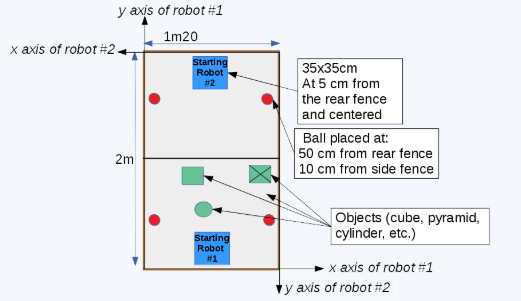
The Battlefield View
Find below the Design steps for the Robot:
In EV3 robotics, a maximum number of 4 motors and 4 sensors are possible to be used.
Since our robot should go over 2 axes, it needs 2 motors for the base system because with 1 motor, the robot could just go forward and backward. By that, we still have 2 motors to be used.
Knowing that the robot should be able to shoot a ball and identify objects at many heights, obviously we thought to build two separate systems: a shooter and a chain for identification. The shooter will consist of multiple Lego parts which turns on a fast speed and kick the ball. As for the chain which can go up and down, will have sensors on it for identification which will be presented in later parts.
For the sensors, since the robot will be working in an autonomous mode, it needs a gyroscope sensor in order to locate its location, using gyroscope for the angle and other sensors (encoders of the motors). For the identification, our solution was to add an ultrasonic (sonar) sensor on the chain since the obstacles to be identified have different height, width and form. The ultrasonic on the chain can go up and down, left and right since the robot can turn and by that, we set some border characteristics for each object.
After this brief introduction, we will explore every part about the robot while talking about:
- Base
- Motors advantages
- Wheels rotation
- Chain
- Shooter
- Differential
- Sensors
- Base
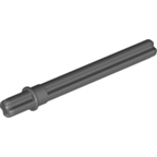
First of all, we are using two wheels on each side and one back wheel as a support for the robot. The middle two wheels, left and right, are connected each one of them to a motor by shafts. In fact, only a shaft can be set inside a motor and this latter will be used to pass the motion to everything connected to this shaft. An example of a shaft can be seen below.
A motor can have a positive or negative power, by that, it can turn in the positive or negative way and this will be set in the code.
So, having one motor on each side, each wheel can run alone. This way, the robot can go to any position. For instance, to go:
| Left motor | Right motor | |
| Forward | + | + |
| Backward | – | – |
| Left | – | + |
| Right | + | – |
Moreover, it could go to any angle we would like by modifying the motor speeds on each side by giving more power on one of the sides.
The base structure of the robot can be seen in the below figures. We can notice the parallelism on the two sides of the robot.
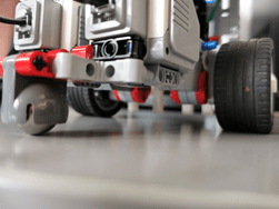
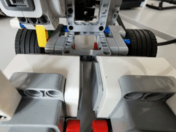
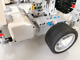
Talking about parallelism, the robot is better if it could be balanced form each side because the weight can affect on the slides of the robot and could cause some problems.
Motor Advantages:
Inside the 4 motors we are using in the robot, there is an integrated sensor called encoder which can give us information on the number of rotations of each motor from which we can get the number of rotations in degrees and could be got in other formats.
Wheels rotations:
In order to know the location of the robot at a specific time, we need a way to find how much distance the robot is spending on each move. To do that, we could base our method on the values we give to the forward, backward and turn functions. But a better method could be to base our code on the sensors, to have more accurate position. By that we mean to use the encoder value in degrees in order to count the distance in centimeters along with our update location thread.
About the wheel:
diameter of the wheel: 5cm-> R=4.5cm-> perimeter = 2* pi* R = 15.7-> 360 unite => 15.7cm-> 1cm=> 22.93
After this calculation, we could work in our code with cm.
- Chain
As we said in the introduction, we designed a chain in order to attach the needed sensors on it and let it go up and down for a specific location.
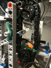
The chain shown in the above figure is constructed using 2 sprockets which are on the borders up and down of the chain to hold it, with 2 shafts to hold the sprockets to the main structure. The shaft from the bottom will also go in the motor which will create the movement of the chain along with the sensors attached to it.
In the figure above, we can see the 2 sensors: sonar and color sensor attached to the chain. Also, we notice a rubber holding the connector between the sensors and the chain which gives a force up, so the sensors won’t create an angle to the bottom and stay straight. When the chain is up, this won’t create any problem and no need for the rubber because of the width of the sprockets that helps.
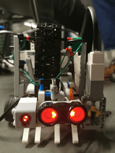
- Shooter
The figure above shows the shooter composed of 4 shooters all connected to the same shaft, same motor. We worked on this design to make very simple by shooting, like a person shooting with its feet.
Differential
We can also notice that the motor is not on the same axe as the shaft, in fact if we put the motor on the same axe, it could have more weight on one side and the motor wouldn’t be protected and the width of the robot would be too big which might could us some problems while moving having obstacles anywhere in the field. The differential in brief transforms the rotation from one axe to another. The kit did not contain a built differential. We used many parts to build one (wasn’t sure if we might find all needed parts but worked with what we have). So, it the motor turns the shaft on the x axe, the shooter shaft on y axe would also turn.
- Sensors
- Sonar
This ultrasonic sensor is normally used to measure the distance from it to another obstacle in front of it (might be difficult if the obstacle have angles). Since we needed to not touch the obstacles, the sonar was used in front of the robot, so it detects any object in front of the object (taking into consideration the border of the field in the code)
Moreover, it was used to identify objects, to differentiate object from each other (seen in later parts).
- Gyroscope
This sensor was used in order to know the direction of the robot for the location update function.
More on the sensors in detail can be seen in the sensors page.
